[ARCH 653] Building Information Modeling in Architecture
Instructor - Dr. Wei Yan
Midterm Project 1 - Parametric BIM
America's Cup Building
1. Introduction
America's Cup Building is located in Valencia, Spain and constructed from 2005 to 2006. Architect 'David Chipperfield' designed this building and he arrayed the unevenly designed floor white decks for the aesthetic aspect as shown in Figure 1. [1]
 |
| Fig. 1. America's Cup Building |
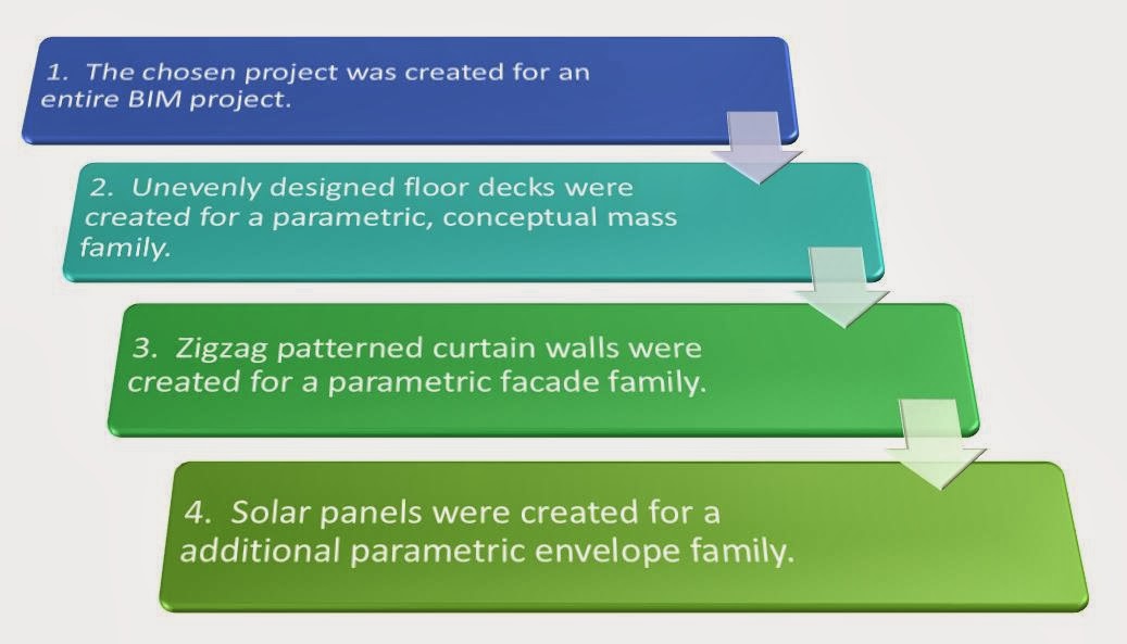
2. Building Information Modeling Diagram for America's Cup Building
(Here, the chosen project was renovated by 3 and 4 slightly to satisfy the requirements of project.)
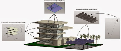 |
| Fig. 2. Conceptual Modeling Steps |
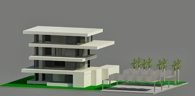
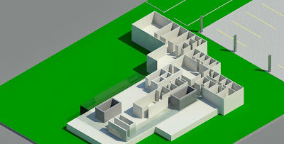
3. Building Information Model Project
Building floors, roofs and interior walls of entire project was created as '.rvt' file type as shown in Figure 3.
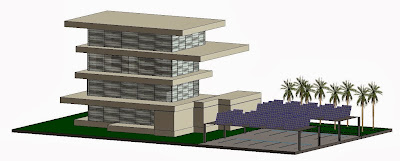 |
| Fig. 3. An Entire Project Building Information Model |
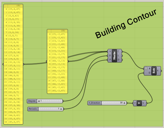
4. Parametric, Conceptual Mass Family
To control and move accurately the mass at the same time, parameters were assigned on each Mass. Since this project was designed with unevenly designed floor deck, every deck should move simultaneously to respect the architect's design. The applied parametric, conceptual mass family is shown as in Figure 4.
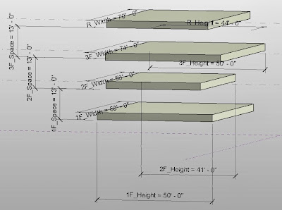 |
| Fig. 4. Parametric, Conceptual Mass Family Model |
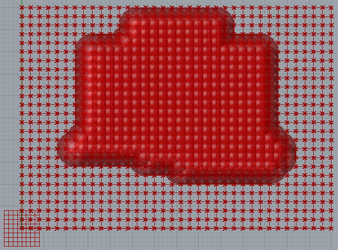
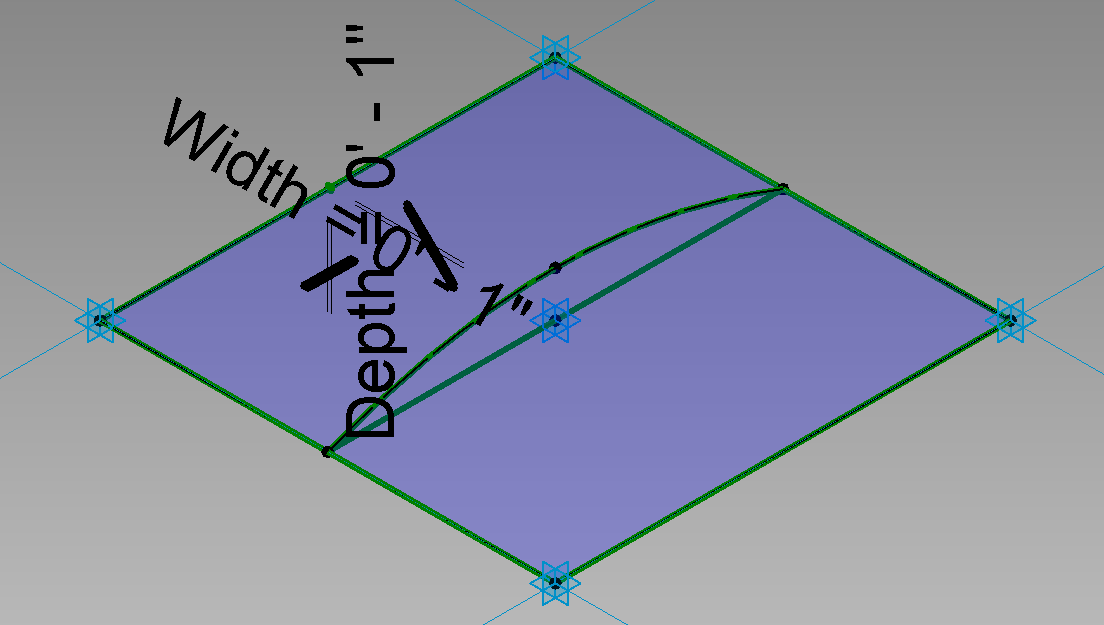
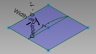
5. Parametric Envelope (Facade) Family
A parametric envelope family was created to applied on the facade of the building. This model was redesigned by the "Rectangle Surface with Curved Surface" to load for the curtain panel family as shown in Figure 5.
 |
| Fig. 5. Parametric Envelop Family |
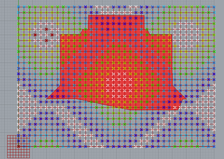
6. Additional Parametric Envelope Family with Equation Description
Solar panel needs to move with respect to the angle of sunshine to collect the maximum energy. The angle of sunshine is different by date, latitude of project, and hours as shown in Figure 6.
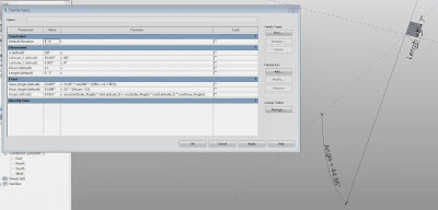 |
| Fig. 6. Solar Panel Model with Family Type |
The solar panel inclination was changed by the following formula.[2] [3]
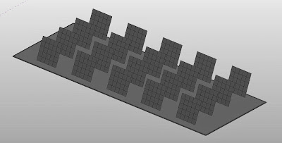
Each parametric solar panel was allocated on the parking lot roof as shown in Figure 7. This prefabricated model was located on the columns.
 |
| Fig. 7. Prefabricated Solar Panels |
However, there are some limitations. In here, n is the day of the year. But it is impossible to pick up the real date. Thus, the number day from the New Years day is punched into the blank manually. For instance, n is 31 for 31 January. Also, hours should be selected from 1 to 24. Lastly, the latitude of the project location is 40 degree North and 4 degree West. Theses limitation can be solved by coding through the Revit Application Program Interface.
7. Rendering Images
 |
| Fig 8. Exterior Rendering |
 |
| Fig 9. Interior Rendering |
8. Video
References